One thing I always wondered, if you go over bore on the cylinder will the oem head gasket hang over? would the piston contact the head gasket? Well, I had the opportunity to check this so I am sharing the info here.
The pictures below are of a 87.5mm cylinder and piston size, the head gasket is a 87mm bore k24a4 head gasket. The bore of the gasket looks just big enough that there is no contact and no over hang. Good to know and peace of mind 🙂


Filed under: stuff
Please note: this is not a instructional post, it is purely another post of what i do during my day to day… just another post on my blog. So if you are looking for a instructional post this is not fully detailed. I do go indepth about all the parts i desolder, and resolder and how to desolder and solder.
I have a few friends purchase the Hondata S300 engine management and required them installed into their ecu’s. This is much nicer than the usual Chrome setup if you have not used it. Just a simple USB wire and you can easily make changes and upload your new map…raise redline, change vtec cross over, change fuel/ignition maps, adjust idle. Way more user friendly than using a emulator to tune, save, then burning it onto a eeprom/chip, and reinstalling on the ecu board.
I’ll start with the ecu board prep. Basically there is a spot on the board that you can de-solder out then later on resolder pins in to install the Hondata S300 daughter board.
You can see here i de-soldered 27256, 74HC373, CN2
Top of the board

Bottom of the board

Then carefully solder in the pins and other components that is required for installation.
Top of the board

Bottom of the board

Hondata also supplies a new Capacitor for location C14 on the board. I have personally seen some of these blow and leave a mess on the board. I’m not sure why they go exactly but they do. If you open the board you’ll know cause it sure stinks.
This is a picture of the culprit

When reinstalling note that there is a pos(+) and a neg(-), so it is directional, there is a neg(-) symbol on the board and on the capacitor itself to let you know which direction it goes.


Please don’t mix these up or you are going to blow something
The next step is to cut the ecu case for the USB interface.
Mark it and carefully cut the opening.


Then reinstall the ecu board and press in the Hondata S300 daughter board to test fit.


Plug in the USB to make sure the hole is big enough and nothing is obstructing.


installed and done 🙂

So Building the K24 Frankenstein i used a 2003 Accord engine which is the K24A4 engine, which uses a oil pump that incorporates a balance shaft for a smoother ride. However, for my application i am looking for power and good lubrication at high rpm’s with having oil starvation issues. The PRB oil pump out of the 02+ RSX typeS has no balance shafts and is meant for the higher rpm’s. So you can benefit from higher RPM operation without issues of possible oil starvation, simpler setup, less weight.
Installing this oil pump is not a bolt on operation. You will need to modify the oil pump for clearance issues. Depending which block you use you may or may not have to shave down parts of the oil pump for it to seat properly. Here are pictures of what hinders the pump from being installed on the K24A4 block. You can see in the middle of the block girdle there are high points that stick up, these are the intrusions that make this install more involved.

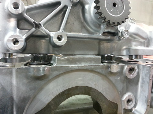
I also have a K24A1 block handy, the 02+ CRV block, it does not have these bumps that get in the way of installing the oil pump. Thus, the 02+CRV aka PPA aka K24A1 block is just a bolt on procedure. I still need to test this to make sure(the main bolts themselves maybe also in the way of allowing the PRB oil pump to seat properly), i will be doing a test fit on a CRV engine block soon and will update this post.

The modifications to the oil pump are minor, basically just trim off just enough to clear the oil pump and your done. Start off with taping up the inlet and outlet ports so no metal shavings get in there.


Mark the area with a felt marker of where you need to trim, then set your pump on a vise or something stable to hold while you grind it down.


Test fit it onto the girdle again, looks pretty good to me 🙂

Here is a picture of a unmodified PRB oil pump vs a modified PRB oil pump to see the difference after shaving/grinding.


Filed under: stuff
Okay, time to put in the pistons. The individual that asked me to put the pistons in wanted to do this on a budget, “cheap as possible build”. I’ve never installed pistons without a hone before. If the rings don’t seal properly you would have low compression and end up disassembling the whole engine again for honing and new rings. The individual said he wanted to try it without the honing and reuse the piston rings, i said okay…he’s the one calling the shots on this build. I personally would not for my own builds. We are also reusing the rod bearings, again something i personally would not do for a build, but since he’s on a budget i’ll try to clean them up best i can.
Lets start.
First off is to clean the pistons, rods, and rod bearings with brake cleaner. I noticed the wrist pins on the pistons were really tight, just a quick spray of the Torco MPZ assembly lube spray and 30seconds later the piston were moving smooth as butter. Awesome stuff and i would highly recommend it.


I used a scotch brite pad with some oil so it was not as abrasive to clean the piston tops and side skirts, then resprayed them down with brake cleaner again for any contaminants.


I lubricated the cylinder walls and the piston side skirts before re-installation. Here is a picture of the cylinder walls, you can still sort of see the cross hatch hone from the original build from Honda.

Once everything was cleaned up i reclocked the piston rings to make sure they were in the right position. When i checked the piston ring clocking position to see how they sat after usage from the old engine setup, they were all off, so just had to realign them. Good thing i checked.


Top and second ring offset

Next thing to do would be to plasti-gauge the rod bearing clearances. Each piston was marked 1,2,3,4 on the domes so they could go back into their original cylinders.
Rod bearing tolerances are as follows.
rod1 .025mm / .001″
rod2 .038mm/ .0015″
rod3 .038mm .0015″
rod4 .038mm / .0015″
Well, within range for the b20z
Clamp the piston rings plop them in, relube the rod bearings with some assembly lube and your ready to go.


Final things left are the oil pump, rear main seal cover, oil pan, oil pickup and windage tray. So next instalment will be the last for this build probably.
Filed under: stuff
I have a old b20z short block that was fully disassembled and ready for rebuild. However, an individual has asked me to reassemble it as is in it’s current condition because of their tight budget. So here is the first installment of the reassembly.
-the cylinder walls are coated with a type of grease to protect the cylinder from rusting, so the first step is to clean up the grease from the cylinders.
-the original main bearings were fairly scatched up from disassembly and storage so i opted to use some new ACL race bearings.
-test tolerances, assembly lube and retorque
-test to make sure crank turns smoothly by hand
cleaning the cylinder walls/block


Cleaning up the journals, seat surface for the new bearings.


ACL race bearings. These bearings are nice, they have a special black coating that helps with lubrication. I also like the grooves in both sides of the lower main bearings. These grooves allow lubricating oils to come in from both sides which the oem bearings do not. Nice design ACL 🙂


Here is a closer look at those lower main cap bearings

Crank shaft journal clean up

Crank thrust washers, i usually put some assembly lube on them so there is little friction on initial startup. The thrust washer if you don’t know is the washer that limits side to side play. Too tighht and it could create friction, too lose and you could get lots of play leading to premature bearing wear.

Here are the factory toleraces for the b20z short block taken from the oem Honda service manual

The toleraces i got from the ACL race bearings are as follows.
1- .050mm
2- .045mm
3- .045mm
4- .050mm
5- .038mm
The results showed a bit on the loser side, but well within the .060mm limit. I have also heard that loser bearing tolerances help with making more power as it can spin more freely within it’s film of oil.
applying assembly lube before installing the crank shaft so that it’s not totally dry and create excessive friction before startup.


Here is a video after everything is torqued up to show how smooth the crank spins 🙂
Next, is to check rod bearing clearances and install the pistons/rings.
From the research i have found, it looks like some hood clearance issues maybe an issue with K swapped cars in civics/integra’s. Even more so with k24 engines, as they are taller.
So, to take precautionary measures i decided to pull off the brake booster fitting on my RRC intake manifold as you can see in the picture below it sticks up quite a bit.

First off you need to remove this piece, it is just press fit in. I simply just twisted it out. Unfortunately my fitting actually sheared off, i used a reverse out drill bit i had and it came right out.


Once it’s out i’m going to seal it with a plug so there is no vacuum leak from this hole. To do so i need to take it to create the threads and that’s it. Simple and easy way to give you a bit more hood clearance with a RRC/RBC intake manifold.


And…. all done 🙂

This install is fairly simple, i cut a gasket for the install and kept the original one as a template so i can cut more later if i wanted to transfer throttle bodies. Basically the kit comes with all the hardware and wiring. Three wires will need to be cut and resoldered on because it uses a different clip, the newer Ktuned version2 uses the oem plugs so new cutting/soldering would be required. Any ways, install the tps on the throttle body, rotate it counter clockwise bolt it down and that’s it, done. Also, when i had my engine harness made i asked them to integrate that clip into my harness so i didn’t have to do any type of soldering with my wiring. Very clean wiring….Thanks Ryan@ RYWIRE


As i was saying before i have 2 gaskets for the throttle body adaptor, one side being 70mm and the other being 74mm. Here are the pictures of the gaskets being installed.

Clean with no lip or hangover on the gasket to hinder flow

74mm gasket test fit for the skunk2 throttle body

Installed Ktuned TPS/gasket and skunk2 tb on next post
So it’s time to install my throttlebody.
The skunk2 74mm throttlebody i have did not come with a gasket, i think they usually do come with it when you buy it from them but either way i’m missing mine so…. what to do.
You can’t just buy a Kseries 74mm throttle body gasket anywhere, I considered ordering a new one but it’d take awhile and most likely a 10dollar gasket would cost 15 to ship which seemed kinda retarded. Anyways, i thought why not just buy a sheet of gasket paper and just make my own. While doing so i thought i’d do some other gaskets as well.
I needed a 70mm throttle body gasket on the RBC intake manifold side, and a 74mm gasket on the skunk2/prb throttle body side. Also, i’ll need a new throttle position sensor gasket anyways. So here are the pic’s.
Oh if you are wondering why i needed 2 different gaskets for the throttlebody, the intake manifold i’m using not the same bolt pattern as the throttle body i’m using. Thus, why i have 2 different gaskets. As well, my intake manifold opening is 70mm and my throttle body is 74mm, also why i have 2 different sizes. The adaptor i’m using is taper ported from 74mm to 70mm creating a venturi effect, speeding up air when going into the intake manifold/plenum.
A roll of gasket paper, i’m sure i can make like 20 gaskets here 🙂


Templates on the left, home made gaskets on the right

Filed under: stuff
I purchased a R-Development Oil pan baffle adaptor. It is convenient in the fact that it is friction fit. You press it into the stock pan baffles and it holds there, when you press it in place the oil pickup neck also locks it in place as well. No welding, no drilling just push it in place and your good. However, i don’t think it works for k20z3 oil pan. Here’s some pictures. Definitely a nice looking billet piece with trap doors and a locking mechanism for the oil pickup neck.


Here is the R development oil pan baffle(Right) installed along side a hytech oil pan baffle(left)

